Fastener inspection · Application proof of concept

Cracked Bolt Head Inspection

A different camera view revealed cracks the first setup could not see.

In a sample-based proof of concept prepared for SSI, top-view testing detected visible head cracks but missed two samples with side-only cracks. Repositioning the camera and retraining for a side view produced reject indications for both samples in the subsequent test.

Recorded inspection view of a cracked bolt head sample
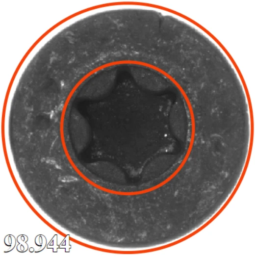
Recorded top-view crack image. The software score is not an accuracy measurement.
Inspection focus
Cracks in bolt heads
Method
Sequential camera-view tests
Stage
Proof of concept

The challenge

The crack needs to be visible

A bolt-head crack can appear on different surfaces. A top view can reveal damage visible from above while leaving a side-only crack outside the camera's view.

The test report documented that limitation in two samples. Their side-only cracks were missed by the top-view configuration, prompting a change in camera position and training.

The approach

Change the view. Retest the samples.

These were separate test configurations: the camera was repositioned and the inspection retrained before the side-view test. Recorded overlays and scores are preserved; the scores are not accuracy measurements.

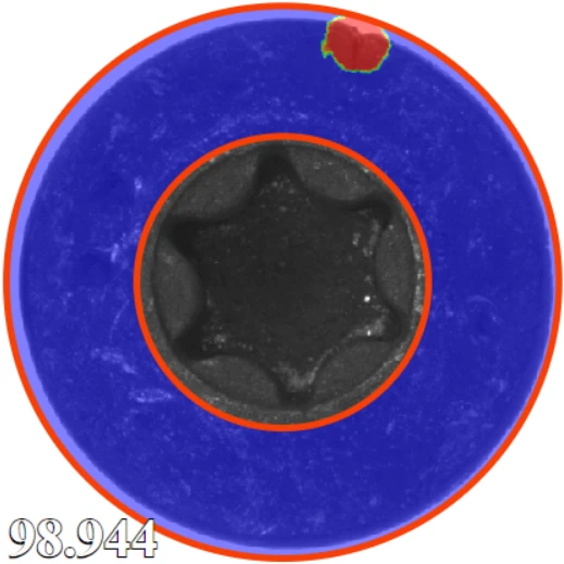
Recorded top-view segmentation of a crack in a selected bolt head

01 · Top-view testing

Visible head cracks were detected

The initial view detected visible head cracks in the tested samples. Two samples with side-only cracks were missed by this configuration.

The result describes the tested samples and viewing geometry.

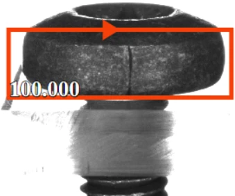
Reconfigured side-view inspection test of a bolt head sample

02 · Side-view retest

The revised view exposed the missed cracks

After the camera was repositioned and the inspection retrained, the report records reject results for both previously missed samples. Recorded indications can still change between Pass and Fail as a defect enters or leaves the camera view.

These are responses to individual frames. A complete-bolt rejection decision was not established.

Recorded test evidence

See the inspection demonstration

This silent, eight-second excerpt shows a selected top-view test followed by a separate side-view test. Source speed and recorded overlays are preserved.

The footage documents the proof of concept. It does not establish production performance.

Recorded sample inspection. Red and green indications are frame responses that change with the visible surface. They do not establish an aggregate rejection decision for a complete bolt. The original top-view misses are documented by the report narrative; the clips are not a recording of those misses.
Visual description

Selected bolt-head samples move or rotate through the camera view. Inspection overlays turn red when a visible defect produces a fail response and can turn green as the defect leaves view. Top-view and side-view footage represents separate test configurations. The report narrative documents the two original top-view misses.

What we learned

Viewing geometry is part of the inspection method

The sample tests show why camera position and training must be considered together. The side-view retest addressed the two side-only cracks that the top-view configuration had missed.

A next validation phase would need to define the required defect coverage, representative samples, repeatability and handling method before drawing conclusions about a production application.

Scope of this case study

This is an inspection application proof of concept. It does not establish an installed simultaneous two-camera system, sustained accuracy or throughput, automated mechanical rejection, or production deployment.